
Kit / Products
Learn everything related to kit sttructure, going from creation to modification!
A - Context
Kits — referred to as Products throughout this document — are a core component of the Ancitrak and ActKloud data structure. They represent a grouping of instruments typically brought together in the operating room and therefore processed simultaneously in the CSSD.
At a high level, a kit is a 'simple' list of instruments (mono or multipart) organized within a nested structure called KBTI: Kit / Box / Tray / Instrument. We have already covered instruments in previous sections; the remaining levels will be detailed in this chapter.
Before explaining how to build kits in Ancitrak, it is important to understand two fundamental concepts: virtual kits and physical kits. Only the first will be covered in detail here, as the second — while useful — is still under development.
Physical Kit"data representation of a real kit"
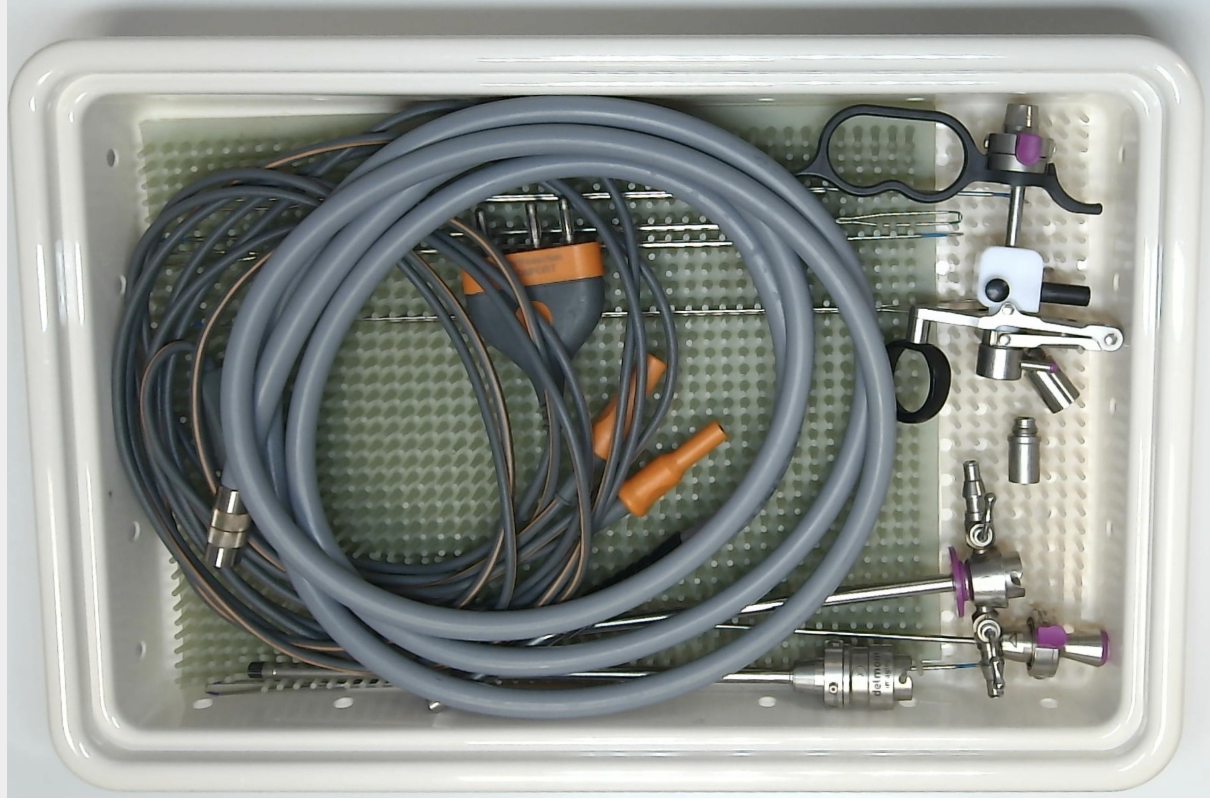
A physical kit refers to the digital representation of an actual kit used in the hospital. It contains the trays, boxes and instruments exactly as they exist and are handled in CSSD and OR. It mirrors the real-world kit with a high level of fidelity and is directly used in reprocessing, tracking, and operational workflows.
This is the data we use every day in Ancitrak to compare against real-world kits and ensure conformity. |
Virtual Kit"data model used for definition only"
A virtual kit is a conceptual definition stored in the system, used to describe the structure, grouping, and logic of a kit. It does not correspond to any real tray but serves as a template or theoretical composition. It is particularly useful for managing replacement or not mandatory parts, which may enter or leave physical trays depending on the instrument’s condition, operability, or availability at control or packing time.
|
Kit
A Kit represents one or more Boxes and contains all the following metadata.
-
Loan Set or Surgical Tray indicates whether the product requires an internal box structure, as is the case for loan sets.
-
Designation (e.g. INCISION HIP)
-
Reference (e.g. 112403), usually used as the kit’s barcode value
-
Ordered (yes/no): indicates whether the kit has a specific spatial layout for instruments inside the trays
-
Supplier Name (e.g. SMITH+NEPHEW)
-
Supplier Reference (e.g. STW-4130.1)
-
Specialty (e.g. Trauma)
- Ordered List of Boxes
- Comment section
Note that a Kit has no picture.
Box
A Box exists only for loan sets and serves mainly as a storage and grouping element; it represents one or more trays and carries only minimal metadata.
- Name (e.g. Cotyle Box)
- Ordered List of Trays
- Comment Section
Note that a Box has no picture.
Tray
A Tray represents a physical layer inside a box (for loan sets) or directly inside a kit (for surgical trays). It acts as the primary level where instruments are actually placed and organized. It carries very few metadata.
|
|
B - Use Cases
Let's pass through the cases where you need to create or modify a kit.
-
You received a new kit and want to digitize its data. The kit does not exist in the cloud, so you must build it from scratch by replicating the composition you physically have in your hands. This does not necessarily mean the process will be long, thanks to the instrument autocompletion feature (link here).
-
You received a kit that already exists in cloud but needs customization. In this case, you duplicate the existing kit and adjust the duplicate to match the physical kit you have in front of you.
-
You controlled a kit and found an issue. You must update or correct its composition to reflect the current physical reality.
C - Features
C1 - General interface
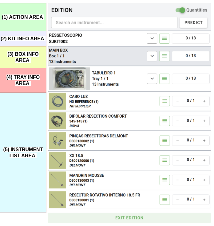
The kit structure is displayed in a collapsible tree view, providing a quick and clear overview of the kit. Each area is clickable and updates the right panel according to the selected element. A row containing instruments will display the total count and the quantity of instruments it includes.
|
(1) Action Area is where we show some usefull information like the stage we actually are and show call to actions buttons. (2) Collapsible Kit Row. (3) Collapsible Box Row (4) Collapsible Tray Row (5) List of instruments.
Note |
 |
===== TEMPLATE =====
A - Context :
Instruments are one of the core components of the Ancitrak and ActKloud data structure. They store all collaborative information required to uniquely identify each instrument among all those in existence. At the writing time of thoses lines there here are the informations that can be gathered.
|
|
 |
B - Use cases :
Identifying a cloud instrument is always done using the Supplier–Reference pair. As a result, the same Reference may exist across multiple suppliers. There is a wide range of possibilities regarding whether an instrument is marked or not. Ancitrak supports four distinct scenarios.
- (1) Supplier + Reference (e.g. Aesculap + FB402R)
- (2) Supplier + No Ref (e.g. Aesculap + NoRef)
- (3) No Supploer + Reference (e.g. NoSupp + 000129)
- (4) No Supplier + No Reference (e.g. NoSupp + NoRef)
Note that Ancitrak and ActKloud always require an identifier. This means that if an instrument is missing either a Supplier or a Reference, a corresponding placeholder value (e.g., NOREF1920 or NOSUPP5939) will be automatically generated by the system. You may encounter this placeholder in various parts of the system.
ActKloud processes instrument references according to its own rules, removing unnecessary spaces, commas, dashes, and other characters. Don’t be surprised if the reference is automatically adjusted to something different from what you initially entered. These internal transformations are normally not visible to users, but this behaviour is completely normal and required for Ancitrak and its internal processes.
C - Features :
One specific aspect of our instrument pictures is the concept of reinforcement. Reinforcement pictures are additional viewpoints of an instrument that are integrated into the database to help the system recognise it more accurately in the future. Note that the main picture (the one displayed in large) is also considered a reinforcement.
C1 - General Interface
In instrument Creation (related to a kit), you will always find 3 visual components for creation. All three areas must be completed with the required information in order to add the instrument.
- (1) Get instrument pictures (or/and reinforcements)
- (2) Indicate Instrument position on tray picture (if specific place) + set the quantity
- (3) Fill the instrument details form
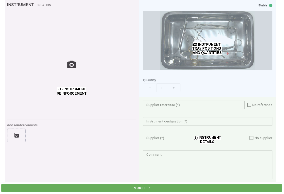
Note at the bottom the Action button, which changes depending on what you’re doing, more on it later!
See below for a detailed explanation of each area.
C2 - Instrument Reinforcement Area
Instrument Reinforcement area correspond to where we can take multiple pictures of an instrument to enhance its recognition. There is 3 states depending on the ongoing actions :
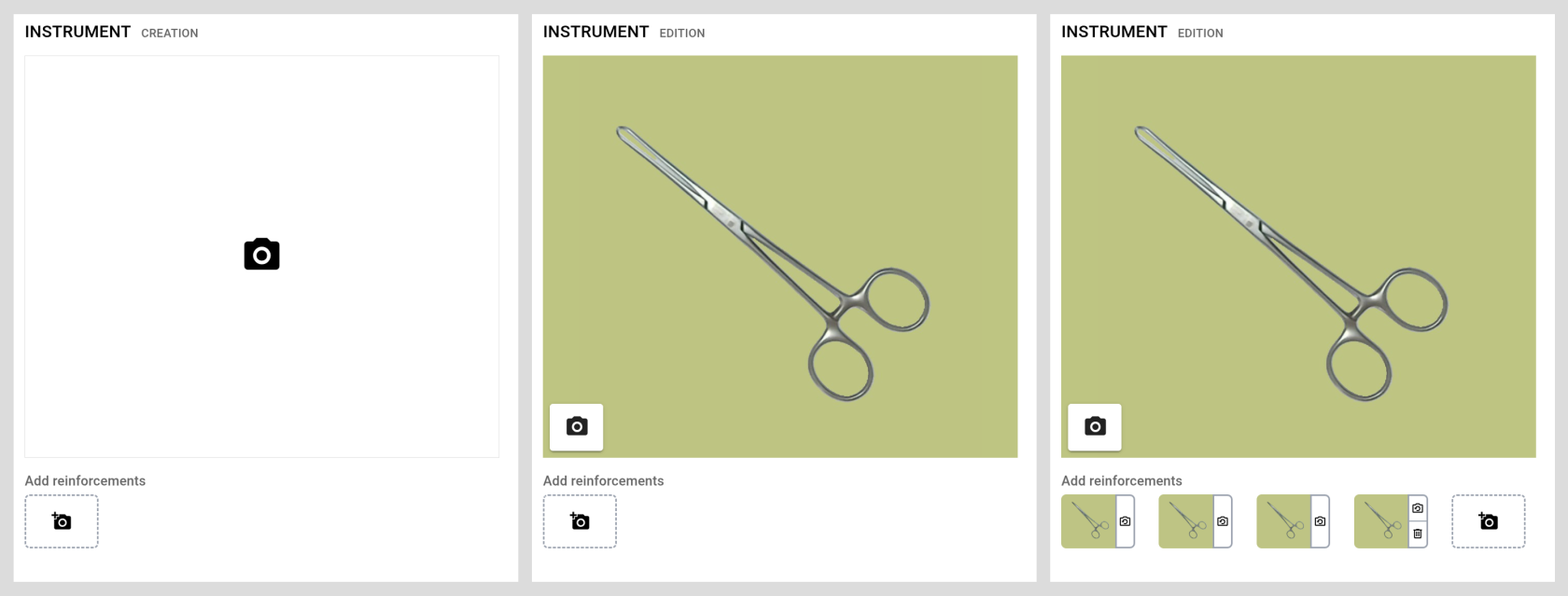
- Left is when the instrument does NOT have any pictures
- Middle is when the instrument exists and there is at least one picture of it
- Right is when the instrument is being reinforced, multiples Reinforcements have been added
Procedure
|
(1) Add first Reinforcement by clicking to the camera icon, the image will appear shortly, as shown below. Feel free to retake the picture by clicking the small camera icon. |
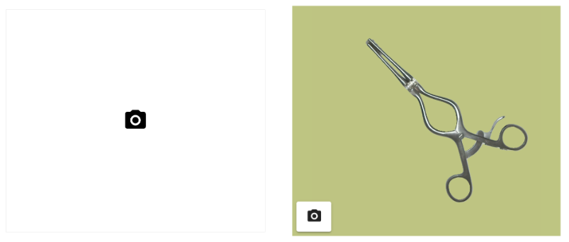 |
|
(2) Add additional reinforcement images by repositioning the instrument and clicking the +camera icon. Each time you create a reinforcement image, you can choose to retake it or to discard/remove it. Its important to move the instrument between reinforcement giving the possibility for the system to view the instrument from it's different perspectives. |
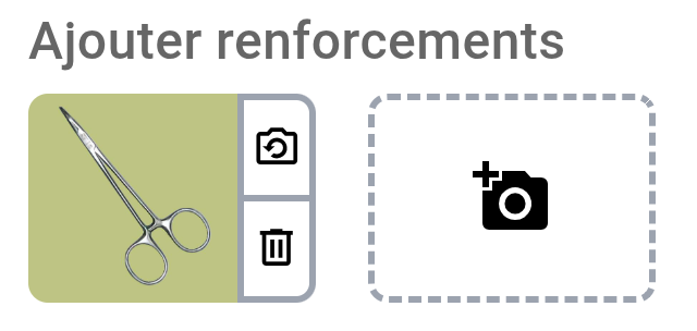 |
Do not open instruments, keep them as they will usually be stored in the container!
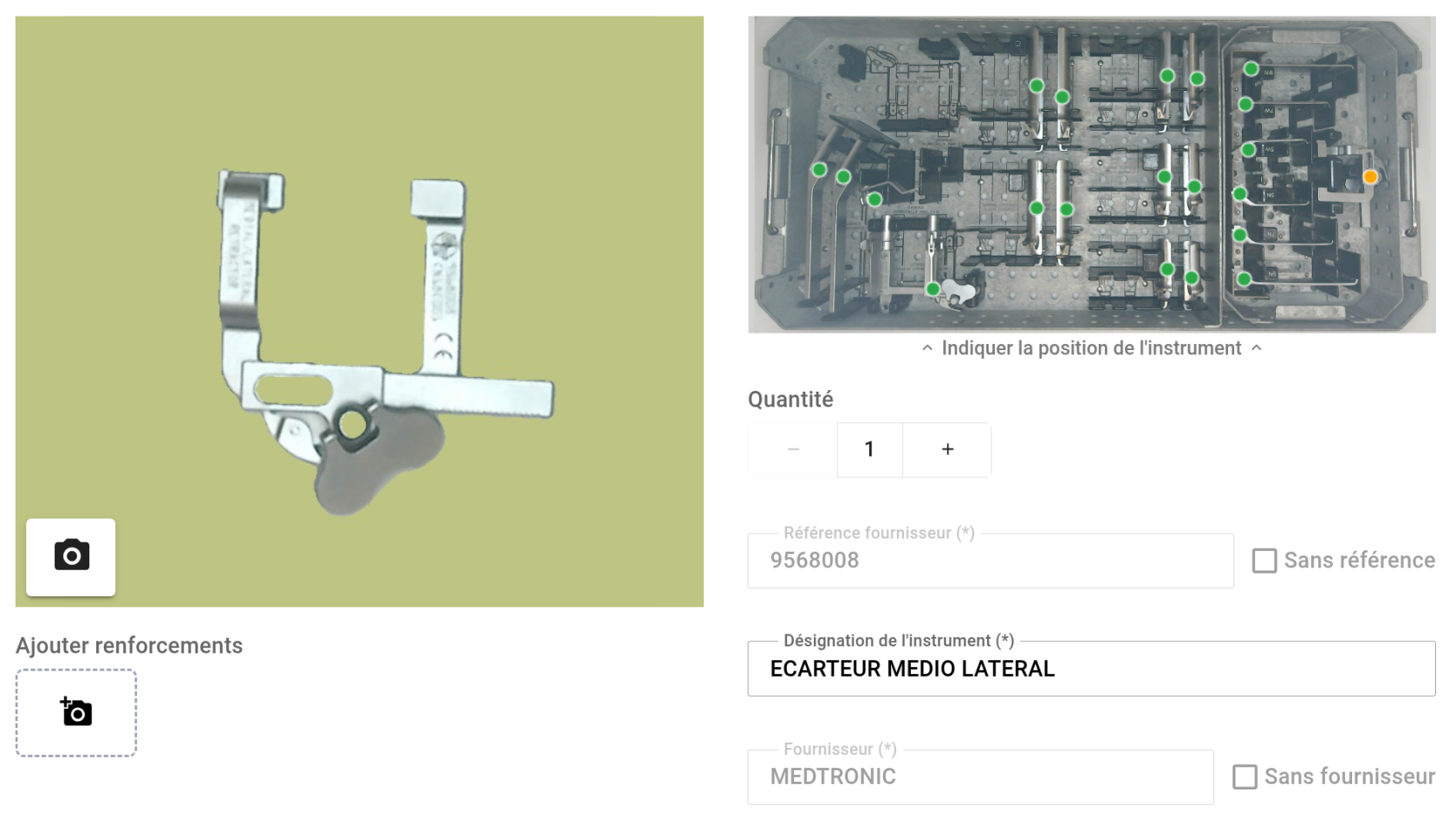
C3 - Instruments tray positions and quantities Area
This area shows where the instruments are positioned in the tray. Placement is done by clicking the location the appropriate number of times, corresponding to the quantity of this instrument in the tray.
Exampe below for one instrument (MEDTRONIC+9568008), one yellow point for ine instrument.
Example below for two instruments (MEDTRONIC+955519), two yellow points for two instruments.
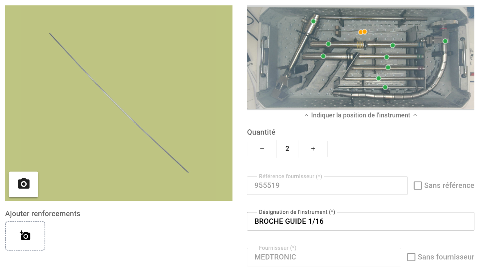
Green dots correspond to other instruments. When hovering over a dot, a small tooltip will display the instrument reference to help with localisation.
Procedure
| (1) Add first the quantity of instrument of this kind in the platform by adjusting the dedicated spinner | 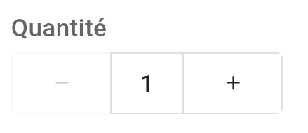 |
| (1) Adjust the position by clicking the map. See below the new position (in gray), the old position remain in yellow until the instrument validation. | 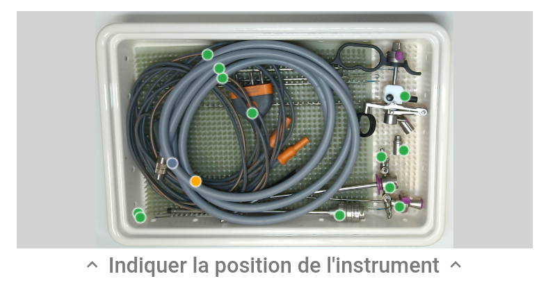 |
C4 - Instruments details Area
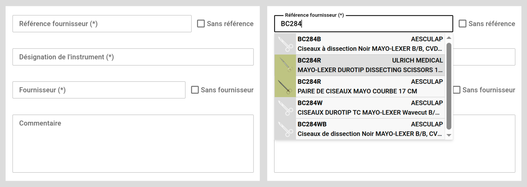
The Instrument Detail Area is a form where all required instrument information is displayed or entered. Depending on the status or the creation step, the form may appear differently, as some fields can be greyed out (disabled from editing) to prevent incorrect usage.
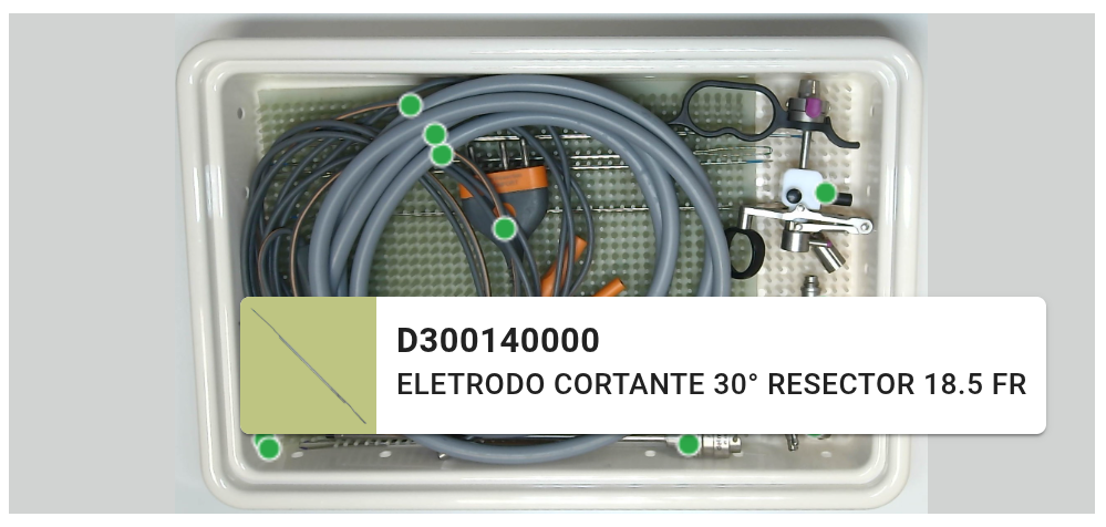
There are two cases—either the instrument exists or not—and as you start typing in the Reference field, the software queries the cloud and displays autocompleted matches to verify its presence.
|
|
In the autocomplete list, some instruments already have images while others do not.
This means the instrument exists in the database but no images have been added yet. In this case, you are providing the first images for this instrument, and reinforcement photos will need to be added. |
Instrument exists
When you select an instrument—whether it has a picture or not—the form auto-fills its values and locks the supplier name and supplier reference fields, while leaving the Designation editable so the user can locally override the instrument’s name within the composition. At this stage, you can also add a Comment that will be shown during the control step.
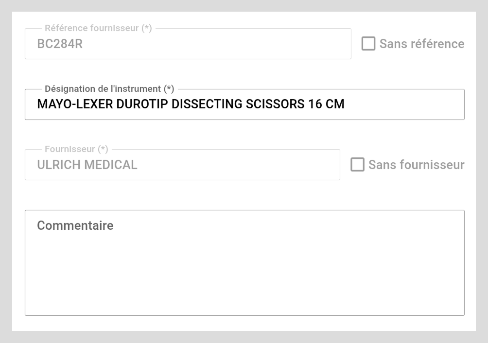
Note that non-editable fields are greyed out. See below for a comparison between a greyed-out (non-editable) field (left) and a normal editable field (right).

Instrument does not exists
If the reference doesn’t appear in the dropdown while typing, the form will wait until all mandatory fields (*) are filled. If your instrument does not have a supplier name or supplier reference, you can tick the corresponding opt-ins, which disable the related text fields, so you don't have to field them.
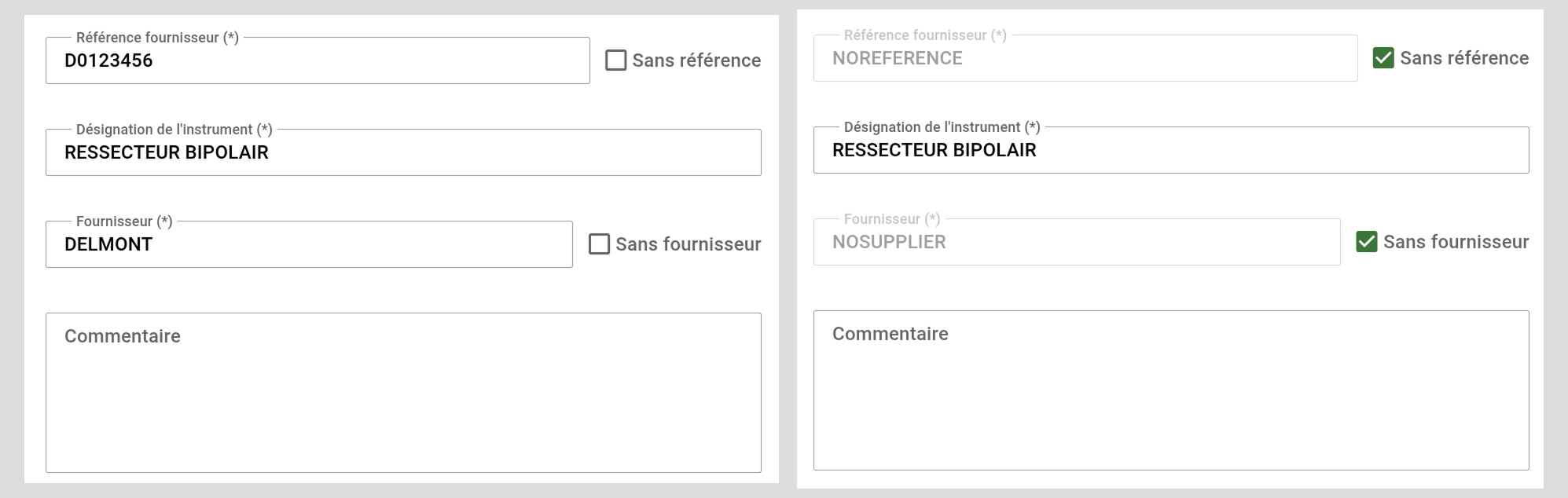
Left image with typed reference, right with no reference and supplier names.
Note that creating a NOREFERENCE will prevent this instrument to ever be find again in autocompletion. While an NOSUPPLIER instrument that still have a reference can be proposed!
Procedure
(1) Type the instrument reference in the corresponding field
(2a) Select the existing instrument and optionnaly overide the designation
(2b) If no instrument is found, simply complete the rest of the form with the designation and supplier name.
This 2b setup is done once and for all: you or your colleagues won’t ever have to repeat this tedious step. This is the power of community! When you lean on the data from the cloud you make sure your reference is normalised accros the network.
C5 - Action Area (bonus)
At the bottom of the screen, you’ll find the validation button. It has two different displays: one when creating or adding a new instrument, and another when modifying an existing one.
1 - Here the create / add shape with a clear action :

Note that when the form in not filled with all the mandatory information it will keep the button grayed out!

2 - Here the modification action :

D - Full procedure
For now, adding an instrument is always done within the context of a composition. This means that when you add an instrument, it is first created, then immediately inserted into the composition. As a result, the add-instrument procedure must be performed during the kit creation process. You can find more details about kit creation here (link).
TODO : add picture to illustrate
For now, let’s sum up the steps to add an instrument.
-
Click the tray’s contextual menu and select Add instrument.
-
Type the first letters or digits of the reference.
-
Select the instrument from the dropdown or complete the form if it doesn’t appear.
-
Add one or more reinforcements, depending on whether the instrument already exists or not.
-
Place the instrument localization on the tray by clicking directly on its image.
-
Adjust the quantity,
-
Once all required fields are completed, the Add button becomes active—click it to proceed.
Also, let's sum up the steps to modify an instrument
- click the instrument you want to modify
- adjust the values according to your needs, usually designation, quantity or localization in the basket.
- Click Modify
Note that, for now, there is no way to delete an instrument from the database. If something is wrong with an instrument, you can either modify it or simply remove it from the composition. The instrument will still exist in the database but will not be referenced in any composition. We periodically garbage-collect these orphan instruments and decide whether or not they should be globally deleted.